


AGUAS DEPURADAS
Execution Methods
1. Trench installation
Within the trench installation it is common to perform supports to reduce the volume of excavation and therefore the surface opening surface in unstable terrain and/or in excavations at a certain depth. These supports are made through the use of panels and struts for those shallow excavations and by sheet piling for deeper excavations in the vicinity of the coast or offshore. The dredging equipment to be used will depend largely on the type of seabed terrain, whether it is a soil or a bedrock.
There is also the case of the use of explosives and/or mechanical equipment for dredging and opening the trench in rocky beds near the coast.

Sheet piling for trench pipe installation
The trench installation not only involves the excavation of the trench, but also involves other works such as the provision of a bed of material generally selected to accommodate the conduction, laying, placement and connection of the pipe, the filling and protection of the conduction and the subsequent restoration on the surface.
2. Trenchless installation
The execution without trench, whose use has been extended and enhanced in recent decades, is often offered as the best alternative for the installation of the conduction in this type of sanitary infrastructures by solving a large part of the environmental problems associated with the use of the trench installation, minimizing the environmental impact, speeding up its installation, extended the useful life of the product pipe and reducing the maintenance costs of the infrastructure.
Within the trenchless technologies, four installation methods stand out, whose choice will depend on the type of installation and the characteristics of the pipeline to be installed:
- SEGMENT LINING – Tunnel execution by lining by segment rings.
- HORIZONTAL DIRECTIONAL DRILLING (HDD) – Horizontal remote control drilling.
- PIPE-JACKING / MICROTUNNELING – Pipe or microtunnel driving.
- DIRECT PIPE – Direct pipe installation.
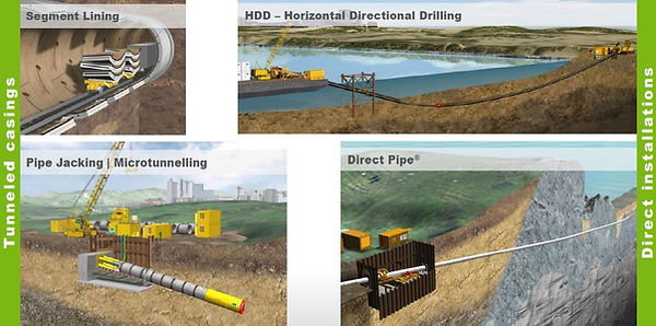
Different types of trenchless pipe installation. Source: Herrenknecht
2.1. SEGMENT LINING – Tunnel execution by lining by segment rings.
Method of tunnel execution by tunnel excavation with a tunnel boring machine and whose lining is done with the installation of segment rings.
The particularity of this type of lining is that the minimum installation diameter is limited to about 2,000 mm, so this lining is discarded for pipes whose diameter is smaller than indicated. On the other hand, there are no restrictions on larger diameters, although current sea outfalls are not usually larger than 3,500 mm in diameter.
The type of TBM generally used in this installation is usually EPB (Earth Pressure Balance) tunnel boring machine, although it is true that other types such as hydroshields, mixshields, etc. can be used.
As a curiosity, the largest diameter sea outfall currently recorded is in Navia (Spain) with a diameter of 8,000 mm.
On the other hand, this installation method is not conditioned by the friction forces originated between the pipe and the ground as with other trenchless installation systems so it has no limitations in terms of length, being able to reach lengths of more than 10 km and does not depend on the installation of intermediate stations as in the pipe jacking/microtunnel driving.
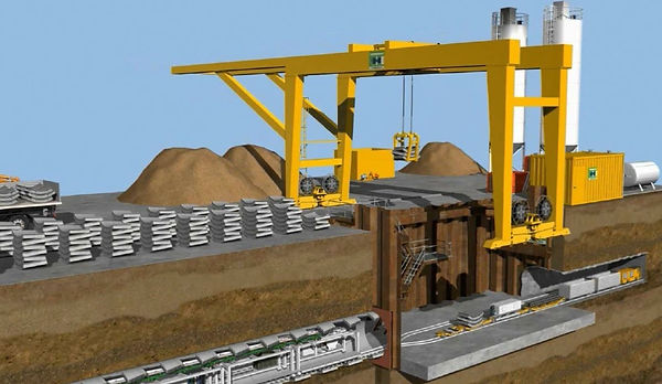
Excavation with a tunnel boring machine by segmental lining. Source: Herrenknecht
2.2. HORIZONTAL DIRECTIONAL DRILLING (HDD) – Remote controlled horizontal drilling
Method of installation of the pipe or product conduction once the drilling phase is concluded. It has certain limitations in terms of installation diameter, with the maximum installation diameter being 2,000 mm and limited in length compared to other trenchless technologies.
The drilling and installation methodology is fast and relatively simple and can be summarized in three phases.
A first phase, known as pilot drilling, in which from a launching pit a first drilling is made directed to the reception pit. The direction of the excavation will be given by the combination of thrust and rotation of the drill head and the type of drill head will depend on both the geology to be drilled and the design geometry of the pipeline.
The second phase consists of scarifying (widening) the pilot drilling through the use of reamers of different diameters according to needs to increase the excavated section until a larger section is obtained than the product pipe to be installed and a last phase that would be the installation of the product pipe by pull back.
During the aforementioned phases, bentonite sludge will be used to keep the excavation open and prevent ground collapse.
Technique of quick installation and less environmental impact as it is not necessary to execute a launching shaft to use, simply launching and reception pits of smaller dimensions and more shallow than the previous ones.
Generally, its use is associated with land crossings such as river crossings and/or infrastructures such as roads, highways, etc., and execution of sea outfalls.
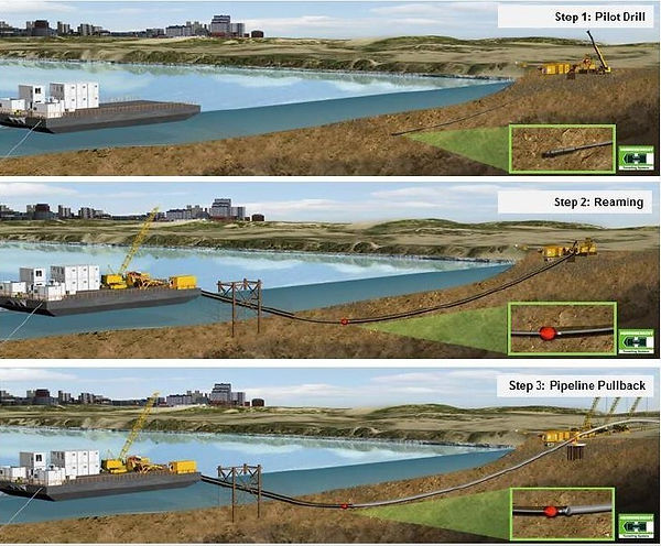
Phases of drilling and installation of pipe for sea outfall by HDD. Source: Herrenknecht
2.3. PIPE-JACKING / MICROTUNNELING – Pipe driving / microtunneling
Method of installation by excavation by tunnel boring machine and whose lining is made by pipe generally of reinforced concrete.
The TBMs associated with pipe/microtunnel driving are usually of the hydroshield type, offering the possibility of installing concrete pipes of various diameters ranging from 250 to 3,500 mm.
The installation is carried out by pushing the concrete pipe from the launching shaft by means of a hydraulic thrust system until reaching the receiving shaft. The length of the concrete pipe to be installed is conditioned by certain factors, mainly diameter to be installed, geometry of the layout, geology, design of the conduction, etc., being of extended use in recent years the length of 4,000 mm for diameters equal to or greater than 2,000 mm.
As in other technologies, the use of bentonite sludge plays a fundamental role in maintaining the stability of the excavation front and in reducing the friction forces of greater importance and weight in relation to the total thrust force to be used.
Unlike the lining by segment rings, in the case of pipe driving, the advance, in this case, thrust is made from the launching shaft to overcome the total force generated by the force on the excavation front and the friction forces acting on the lining. In order not to exceed the resistant capacity of the concrete pipe, it is common practice to install intermediate jacking stations (intermediate stations). The spacing between stations is usually around one hundred meters.
Through the use of this technology it has been possible to execute considerable lengths that seemed unattainable due to the constraints of the technology itself, mainly due to the impact of frictional forces during the push of the pipe on the ground.
As a reference, in 1994 the submarine pipeline known as Europipe was executed with an inner diameter (ID) of 3,000 mm and whose length reached 2,535 meters, although it is true that it is not properly a sea outfall by definition, it is still a submarine pipeline executed by means of pipe driving and that serves to understand the possibilities of this technology applied to the installation of sea outfalls.
From that date the number of submarine pipelines executed by means of pipe driving has continued to grow to such an extent that in the last decade and until 2022, at least four (4) other submarine pipelines have been executed, three (3) of them, sea outfalls with internal diameters equal to or greater than 2,000 mm and whose lengths are around 2,000 meters, listed chronologically below according to year of completion.
Sea outfalls:
• Sochi Black Sea Outfall (Russia) – ID2000 mm and a length of 2,014 meters (2013).
• Emergency Sea Outfall (Kuwait) – ID2200 mm and a length of 1,950 meters (2022).
• Sorek II Sea Outfall (Israel) – ID2600 mm and a length of 2,023 meters (2022).
Connecting submarine conduction (Landfall):
• Altamira Landfall (Mexico) – ID2600 mm and a length of 2,246 meters (2018).

Phases of drilling and installation of pipe for sea outfall by HDD. Source: Herrenknecht
2.4. DIRECT PIPE – Direct pipe installation (Herrenknecht)
The method known as Direct Pipe is born from combining the advantages of the microtunnel and the HDD to install the product pipe in a single phase by carrying out the excavation and installation of the pipe by pushing simultaneously, allowing to accelerate the installation process.
The excavation is carried out by means of a tunnel boring machine type hydroshield (pipe jacking/microtunnel) to which the pipe to be installed is connected by sections of variable length according to the platform available on the surface, being able to connect sections of great length thus reducing the number of connections on the surface.
All the facilities necessary to operate the TBM are housed inside the product pipe and are recovered by pulling back once the final excavation position is reached.
This type of trenchless technology does not need a deep launching shaft when placed close to the surface nor does it require a reception pit, making it a perfect alternative for the execution of sea outfalls.
The range of diameters to be installed varies from 800 to 1,500 mm and can reach great lengths as evidenced by the longest section currently executed, 42-inch sea outfall executed in Auckland (New Zealand) where 1,930 meters were reached.
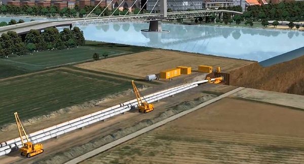
Pipe installation using Direct Pipe. Source: Herrenknecht
2.5 Laying pipe on the seabed
Another installation method is the laying of pipes on the seabed usually used offshore as an extension of the pipeline already installed by other methods discussed above and / or as a single installation method in areas with complicated or abrupt seabed orography very close to the coast.
Generally, the most used material in these cases is HDPE pipe (acronym in English of high density polyethylene), the installation is done by subsidence of pipe sections that can reach up to 500 m in length, the installation diameters usually used range from 1,600 mm to a maximum of 2,500 mm.
The most used method for its installation is towing and subsequent sinking.
The pipe with ballasts and filled with air is towed floating to the position established for sinking and placement according to design.
The anchoring method, known as "S" shaped anchoring, is carried out by means of the progressive flooding of the pipe process controlled by valves that allow the entry of water at the end to be sunk and air exit through the blind flange at the other end.

Method of anchoring in the form of “S” by progressive flooding
In order to minimize and reduce the stresses on the pipe during the sinking phase, an axial force is usually applied to the free end on the surface to smooth the "S" shaped curve as well as the use of floats or devices in the section to be sunk to seek the same result so that the stresses on the pipe are reduced and the resistance of the material is not exceeded at any time. nor the permitted strain limits.
The use of ballasts, usually reinforced concrete, is necessary to maintain the conduction in its design position and prevent it from floating or moving by the hydrodynamic forces of the seabed.
In addition to the type of installation discussed above, other installation methods can be added, although it is true that of less use, such as the placement of pipe to pipe on the seabed and by bottom dragging launching the sections of pipe from a launch ramp generally installed on the coast and offshore.
3. Advantages of the microtunnel
-
Very versatile technology adapted to all types of geology and suitable in the presence of high phreatic pressures.
-
Greater security compared to other technologies.
-
Versatility in terms of diameter and length of the pipe to be installed.
-
Less impact on surface both in area of occupation and in affection to other facilities, services, etc.
-
It requires a smaller volume of excavation and therefore the volume of excavated material to be transported is reduced.
-
Lower environmental impact, of utmost importance in sensitive and/or protected areas.
-
Independent of weather conditions and sea conditions.
-
Quick installation.
-
It offers better protection of the conduction against waves, erosion and drag damage when installed under the seabed.
BIBLIOGRAPHY
-
Marine Outfall Construction. Background, Techniques, and Case Studies by Robert Grace. ASCE Press – 2009.
-
Offshore meets Onshore: Trenchless solutions for pipeline landfalls - Michael Lubberger, Herrenknecht AG. October 2018.
-
Herrenknecht Sea Outfall References_Pipe Jacking - wet recovery.
-
HERRENKNECHT DIRECT PIPE® One-pass trenchless installation of pipelines in all geologies.
Websites:
herrenknecht.com
victoryepes.blogs.upv.es/2013/08/30/los-emisarios-submarinos/
trenchlesspedia.com