


MONCÓFAR DESALINATION PLANT. CASTELLÓN (SPAIN)
The construction of the Moncófar Desalination Plant (Castellón) was executed during the period 2011-2012 at the request of Aguas de las Cuencas Mediterráneas (ACUAMED) to solve the problems of drinking water supply of the populations of Moncófar, Chilches and Almenara in the province of Castellón, due to the problems derived from the water catchment from wells of salinized aquifers because of marine intrusion caused by their overexploitation. The construction was awarded to the joint venture IDAM MONCOFA composed of Isolux Ingeniería, OHL-INIMA, FACSA and RENOS, with the subcontracting of the execution of the sea outfalls to the company EUROHINCA (Europea de Hincas Telemando S.A.U.).

Image 1: Moncófar Desalination Plant entrance.
WHAT?
Feed and brine system of the Moncófar Desalination Plant in Castellón, through the execution of two tunnels executed with a tunnel boring machine with submarine recovery.
WHO?
Client
AGUAS DE LAS CUENCAS MEDITERRÁNEAS (ACUAMED)
Main Contractor
UTE IDAM MONCOFA (Isolux Ingenieria, OHL-Inima, FACSA Y RENOS)
Microtunnel Contractor
EUROHINCA (Europea de hincas teledirigidas S.A.U.)
WHEN?
Between January 9th and February 29th of 2012, the brine line was executed in pipe jacking methodology with an inner diameter of 1,200 and a length of 440 m.
Between April 12th and May 31st of 2012, the feed line was executed with an inner diameter of 1,500 mm and a total length of 440 m.
Subsequently, the desalination plant developed the functional tests, but it was not commissioned until March 2019.
WHERE?
Moncófar, Castellón, Spain.

Image 2: Project location at Moncófar beach, Castellón.
WHY?
The Moncófar Desalination Plant was built with the aim of desalinating and conditioning seawater for the supply of drinking water to the towns of Moncófar, Chilches and Almenara in the province of Castellón. The overexploitation of the wells in the area caused a marine intrusion affecting the existing aquifers, salinizing the water and making it unusable for human consumption, which led to the approval of the construction project of the Moncófar Desalination Plant.
The plant was designed for an initial production capacity of 30,000 m3/day that allowed the contribution of 9.90 Hm3/year of water for human consumption, expandable up to 60,000 m3/day according to future supply needs.

Image 3: Aerial view of the Moncófar Desalination Plant.
HOW?
The inflow and discharge system of the Moncófar Desalination Plant is composed of two lines: a sea outfall to take sea water (water to be desalinated) and an outfall that pours the rejection water (brine). Both pipelines are composed of two sections, onshore and offshore sections. The offshore sections were built by combining a first stretch of microtunnel, using the seawater pumping station as a launching shaft for both, with a second section executed by dredging, installation of HDPE pipe and capping.
The sea outfall consists of a first section executed in microtunnel with reinforced concrete pipe with an inner diameter of 1,200 mm and an outer diameter of 1,500 mm. The pipeline continues until connecting with the diffuser section with HDPE (high density polyethylene pipe) according to the following table:
KP
Material
Ø inner [mm]
0+000 – 0+440
Reinforced concrete
1.200
0+440 – 0+906,6
HDP SDR 26
1.108,2
Likewise, in the case of the inflow, the first section was executed in microtunnel with installation of reinforced concrete pipe with an inner diameter of 1,500 mm and an outer diameter of 1,840 mm; while the connection with the intake tower was made with HDPE pipe:
PK
Material
Ø inner [mm]
0+000 – 0+440
Reinforced concrete
1.500
0+440 – 2+050
HDP SDR 26
1.293
The layout of both jacking pipes is parallel, taking advantage of the seawater pumping pitcher of the desalination plant as a launching shaft. It is a screened enclosure under the water table located just 100 m from the shore of the beach.

Image 4: Control container.

Image 5: Launching shaft / seawater pumping shaft
Both tunnels allowed the client to overcome the wave breaking area on the coast facilitating the execution of these sections. Firstly, it was executed the sea outfall with 1,200 mm inner diameter and later the one with 1,500 mm inner diameter.

Image 6: TBM lifting.
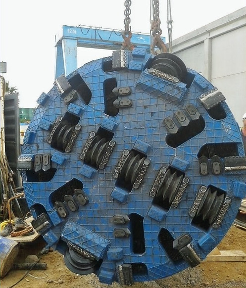
Image 7: Cutting wheel.
Few meters far from the exit of the launching shaft, buoyancy problems appeared due to the passage through a marsh area did not detect during drilling campaign. It was solved by adding weight into the pipes by the positioning of metallic platforms.
Foto 7: Vista del giroscopio montado en la tuneladora encima de la diana del ELS que utiliza el guiado láser.
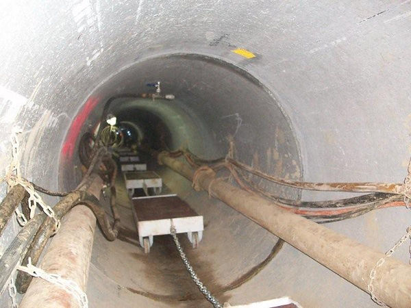
Image 8: Metallic platforms to avoid buoyancy.
Once both tunnels were completed, the machine was recovered with marine means and transported to the Burriana Port where it was hoisted and loaded on a platform for transport.
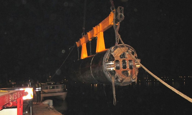
Image 9: TBM recovery after sea outfall execution.
Jorge Martínez Benita y Fernando García-Ruescas Cazorla
TUNNELS TECHNICAL DATA
SEA OUTFALL - BRINE
Length
440 m
Inner Diameter:
1200 mm
Outter Diameter:
1500 mm
Slope:
0,42 %
Geology:
Very fine sands with gravel and marsh areas
Starting level:
-6,59 m
Final level:
-8,29 m
TBM:
Hydroshield AVN
Intermediate Jacking Stations:
5
SEA OUTFALL - FEED
Length
440 m
Inner Diameter:
1500 mm
Outter Diameter:
1840 mm
Slope:
0,40 %
Geology:
Very fine sands with gravel and marsh areas
Starting level:
-6,62 m
Final level:
-8,29 m
TBM:
Hidroescudo AVN Herrenknecht
Intermediate Jacking Stations:
5
BIBLIOGRAPHY AND LINKS